
The tree is a 3D tool to generate 3D structures within the boundaries of the image. These structures can be created by clicking directly on the renders and saved for later loading. This tool allows you to simultaneously handle up to five trees.
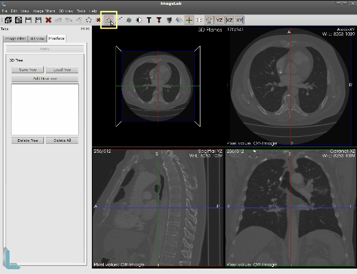
The button on the taskbar that is used to enable the interface for entering the 3D tree is highlighted in yellow in the picture above. While on the icon is highlighted when disabled is to look the same from others. If the tool has already been used when the button turns off the tree and 3D renders are removed from all structures and the interface on the left side.
Activating the button again the tree all the 3D structures as well as the interface to be shown again left with the same settings since the last time they were used, but the case is finalized ImageLab settings will be lost. All interactions with the mouse made ruler 3D using the left mouse button. The insertion of the joints is done only renders in Axial, Coronal and Sagittal and is shown only in 3D rendering tool for spatial visualization.
.png)
In order to get the insertion point in the render, you have to activate the button “Add New Tree.” It will be then generated a tree with name Untitled simply just click on pay now to start entering the dots.
.png)
Under each click that occurred within the range of the image is inserted a dot representing a tree node. In the picture above to see the inclusion of three points in sequence. Upon insertion of each point, a line is drawn between them, with the bottom line with color stand out.
.png)
To insert a branch, you must click on a node, chosen to contain more than one descendant node. Once that’s done click anywhere on the surrender to choose the position of the second descending node chosen. This will create a branch with two descendant nodes of the chosen node, as seen in the figure above.
.png)
Under each click that occurred within the range of the image is inserted a dot representing a tree node. In the picture above to see the inclusion of three points in sequence. Upon insertion of each point, a line is drawn between them, with the bottom line with color stand out.
.png)
You can also create more than one branch. Just click on the same node previously selected and then click another point of surrender to add the third node descendant of the chosen node. The branching process has no limit and can contain the chosen node “n” branches. The figure above shows the process of inserting the third down.
.png)
As shown above, new branches can be created. In this figure, the yield of Axial slice was moved from number 170 to 245 and this new branch nodes were included in this slice. In 3D rendering can see how the spatial position of right-handed procedure.
.png)
Clicking on any point or line of the tree, you can move them anywhere within range of the image. In the figure above the highlighted line has been moved down, bringing with them two points related to it and consequently all the lines that relate to these points. The same happens if you move just one point.
.png)
Pressing the “Tree Save” in the left interface, you can save the tree file in vtk. In the figure above the tree is being saved with the name Tree1. This name replaces the name Untitled in the left interface, which will now contain the actual name of the file.
.png)
You can also create more than one tree to be manipulated. As the figure above another tree was created following the procedure of creating the tree and saved by following the procedure of saving the tree that have already been explained above. These trees are independent and make up two different files.
.png)
To switch between editing and Tree1 tree2 is necessary to choose which tree will be edited.
Just make the choice of tree to be edited in the left interface. As shown above, the Tree1 is selected and now all the clicks will be directed to surrender her tree2 disabled for getting the clicks. If you click on the yield is given, a new node is inserted, if the click is at some point or the tree line, it may be moved.
.png)
As shown above, the interface left before the file names, there is a check box. This box is used to enable / disable the display of each tree.
This figure was Tree1 is temporarily disabled and invisible. Enabling the check box again, the tree will be displayed again in the renders. This can be done to any tree at any time including all the trees that are invisible at the same time.
.png)
Pressing the button “Load Tree” on the left interface, you can load a previously saved tree file in vtk.
In the figure above tree3 will be charged. This name will be placed below the left tree2 interface and can also be manipulated to the two previous trees. Recalling that as mentioned earlier, only 5 trees can be handled simultaneously.
.png)
Pressing the button “Delete Tree” on the left interface, you can erase the tree that is Orange selected in the interface itself, as shown above.
.png)
The figure above shows the “Delete All” highlighted, which is used to erase all the trees of the list at once.
![]()
![]()