
The ruler is a 3D tool to make measurements on images and can be used across theboundary of the image within the 3D environment. She is articulate and serves tomeasure the distance betweeneach of its joints and the total distance between the firstand any other joint.
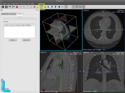
The button on the taskbar that is used to trigger the insertion of 3D ruler is highlighted in yellow in the picture above. While on the icon is highlighted when disabled is to look the same from others. If the tool has already been used when the button turns off the ruler 3D renders are drawn from all points and lines of the ruler and its 3D interface is removed from the left side. Activating the button again ruler of 3D points and lines as well as the interface to be shown again left with the same settings since the last time they were used, but the case is finalized ImageLab settings will be lost. All interactions with the mouse made ruler 3D using the left mouse button. The insertion of the joints is done only renders in Axial, Coronal and Sagittal and is shown only in 3D rendering tool for spatial visualization.
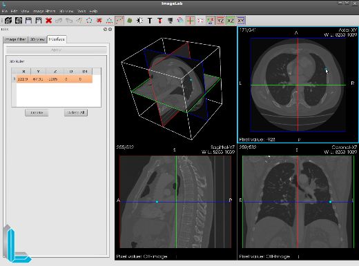
When the ruler 3D is activated under each click occurred within the range of the image is inserted into a point that represents an articulation of the ruler. In the picture above tosee the first click enters the starting point of measurement in the left table you can seesome information relevant to the point inserted: the coordinates “X”, “Y” and “Z” respectively, the distance “D” that point to its predecessor, and the total distance “DT”that point to the first point. As this was the first point, the two distances mentioned have value 0.

As we can see in the picture above, the second click is inserted a new joint. The two points are then connected and information is displayed along the second point. Such information is to measure the distance between two points, and is being used the millimeter (mm) as the unit of measure. As more clicks are being given a few other joints will be inserted sequentially inserted at the last joint.
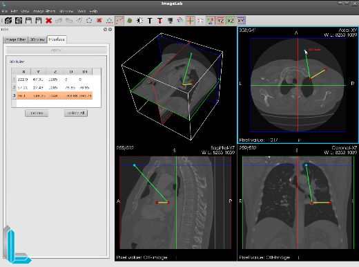
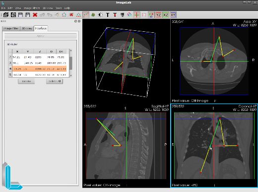
As you can see in the picture above, the third click is inserted a new joint. In rendering the Axial slice was moved from 171 to 308 and the third joint was inserted in this slice. You can see in 3D rendering the spatial position of any rule.
This time can also be seen that the lines connecting the dots in different colors as well as one of the points. That’s because the last point clicked or is created with the color blue than the red color of other points as well as the previous line to the last point that is clicked with the color green, yellow respectful of the other lines.
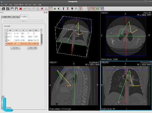
As you can see in the picture above, the fourth click is inserted a new joint. This time click on the surrender was given Coronal and as you can see in 3D rendering, the line connecting the last point unser the ruler crosses the slice that represents the Sagittal surrender. This is because the rule concerns only the coordinates it imposed. The table left, we see these coordinates “X”, “Y” and “Z” and the distance “D” representing the distance between this outcast, last inserted point and its direct predecessor and the total distance “DT” which reprresenta distance inserted between the last point and the point of origin of the ruler, ie, the first point entered.
Clicking on any one point of a line, a joint is created at this point on the line. With the insertion point of the new measurements are automatically updated as soon as the queue of points while maintaining the order of points on the ruler.
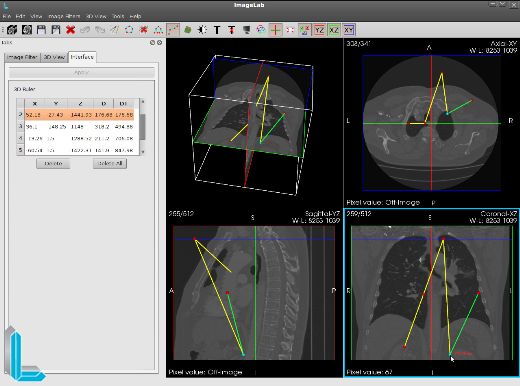
You can also select and drag any of the joints inserted into any surrender. The point clicked will change color as well as their previous line. All coordinates and measurements are automatically updated as the move happens. In the figure above the second point was moved by a great distance. Its coordinates and its distance as well as the distances of all who depend on it are updated in the table and surrender.
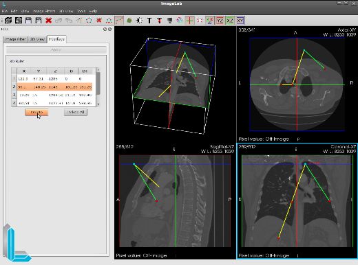
When we delete a point using the “Delete” button located below the table on the left, this point is removed from the list that makes up the table and it is reordered. The same happens with the ruler, all points are deleted to the point later date. With the departure of point 2, its button (1) and its predecessor (3) are interconnected while maintaining the consistency of measurements and their ruler.
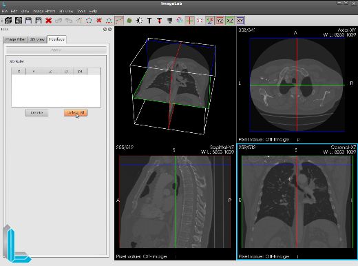
In the figure above all points have been deleted using the “Delete All”. In this case all points are deleted, and no rule is shown in the renders.
![]()
![]()