
Open the image of work (details of how to open an image in ImageLab see here)
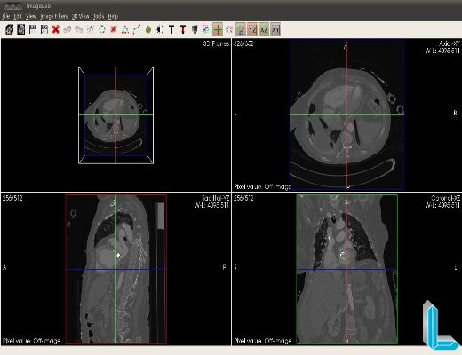
Once the picture opens, we have the following view:
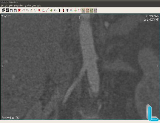
In this tutorial, we want to segment the structure related to the aorta. For a better view of the structure of interest is zoomed (shift key + mouse wheel) in the vision “Coronal” and notes that the image is very pigmented (which makes the segmentation process). Thus, it is necessary to apply a filter to improve itself before starting the segmentation process:
As the image enhancement filter selects the median filter (menu “Image Filters” – “Neighboorhood” – “Median Filter“) as it preserves the edges of the structure of interest. In this case, choose the size of the convolution mask (one (1) for the three rays) and so it is possible to envision the region of interest more smoothly:
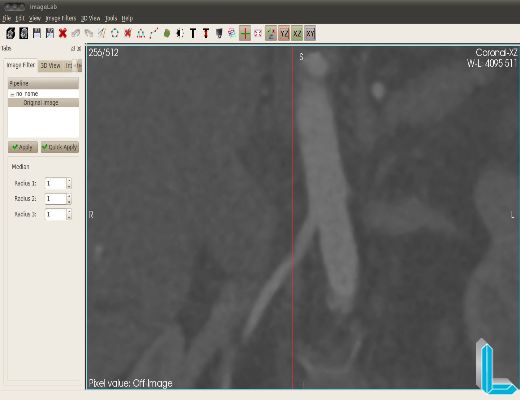
After the improvement process, the image is ready for the segmentation:
In this tutorial we will apply the filter ITK Connected Threshold (menu “Image Filters” – “Segmentation” – “Connected Threshold”) which is a growth region from the seeds specified by the user. Those pixels that have intensity within the search range specified by the user, will have its value changed to a specified value. Since the pixels that fall outside the range will have its intensity value to zero.
The filter has the following parameters:
Lower: lower value of the range search.
Upper: upper value of range search
Replace: the pixels that are within the range of intensities will have their values changed to this value.List of seeds: seeds specification where the filter will begin to be processed.
They should be applied on regions of interest.
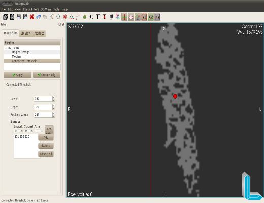
Passing the mouse over the region of interest, one can see that the range of intensities varies (for the structure of the aorta) approximately 330-380.
To specify the seed, you should click the “Add” and then click on the image.
In the image below you can see a seed placed in the position given by coordinates “272 255 204”.
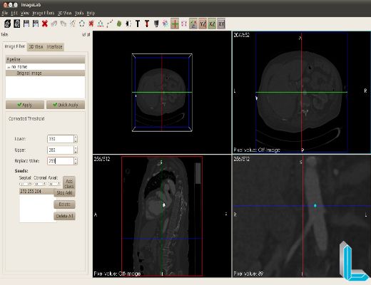
The value of “replace” is specified as “255”.
Applying the filter with this configuration, we have targeted the following image:
Note that depending on the range of values are very close, the segmented image was greatly missed (holes or islands). We can increase the range to 310-400 and segmented image is as follows:
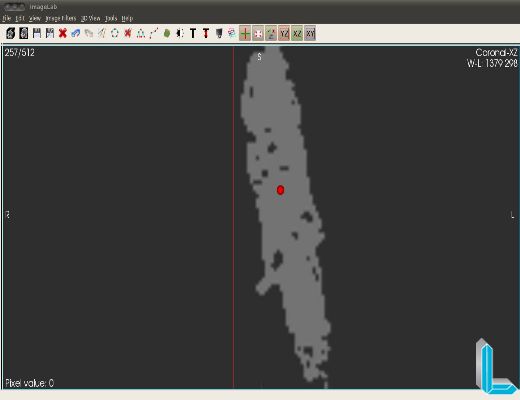
Importantly, the greater the range of values, the additional structures (trash or unwanted structures) can be produced.
Creating a surface mesh:
Now, if you want to produce surface mesh according to the previously segmented image.
For this, go to the menu menu “3D View” and select the “Contour“.
As the segmented image has only two shades of gray (0 to 255), the option “Add Value” put the value 255 and press the “Add“.
Press the “Apply” and after the processing period, the surface mesh is rendered for viewing the 3D preview window.
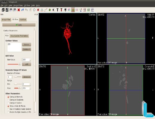
The screen currently displayed can be saved in VTK format (unstructured grid) via the “Save Mesh“.
![]()
![]()